Design Reviews and Lessons Learned
With design coming to a close for EV5, I’ve learned a lot about aerodynamic design and project management. This post aims to recap the 3 design reviews we have had this past season and summarize the lessons learned.
I’m being very wordy with this one, less images. Hope this is insightful nonetheless.
September 29, 2023: Meeting Danny Jierian
After FSAE Michigan EV 2023 I was informed from Jordan Van Dam (thermal management wizard) of the existence of Danny Jierian (professional thermal management wizard) who turned out to be one of the most influential factors in the development of EV5’s aerodynamics package.
The goal of this first meeting was to determine whether or not our level of justification as a first-year aero team was good, and if we were even on the right track with our approach.
15 minutes in and we started talking about tires, from which we received nods of approval to indicate we are indeed on the right track. “All aero judges are tire judges,” he says.
Further praise was received when we talked about our MATLAB lap simulation program which was used to determine our ClA and CdA ceilings. There’s a specific FBD he really liked that we should include in our files to show at competition, shown below.
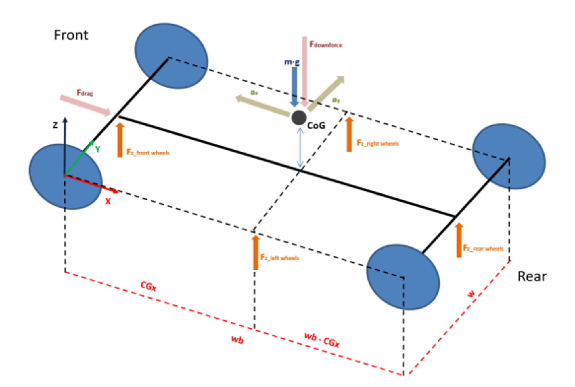
Fig. 1 FBD showing all forces taken into consideration in MATLAB script. Image courtesy of Sepehr Makarian Abdolahi
This concluded our talks about justification, then we moved onto where our design was at so far. Starting with airfoil selection, his first suggestion was to add a legend to the plots and/or export the plots into Excel so it would be much more clear to read. This I was expecting to hear and plan to implement next year, I just didn’t have time this year due to having to build up both the design, and subteam infrastructure, from scratch after 3 years of inactivity.
Another comment he had about our airfoil selection was we included Reynolds numbers which ranged from 3-5m/s for our chosen chord lengths. This is when he made me realize that aerodynamic grip is negligible at these speeds compared to mechanical grip, so our search for airfoils should primarily be conducted around 15-20m/s. This was a good point which I fully agreed on.
I briefly touched on manufacturing to explain that we are doing a mouldless construction this year to save money and man-power. He liked this.
For the latter half of the meeting, he really started to emphasize the importance of an undertray. I already knew a sculpted floor is the best bang for buck when it comes to L/D, however he opened my eyes to just how effective it can be when done right.
The meeting ended with him telling us just how proud he was that he didn’t see or hear mention of 3D CFD after an hour-long talk. This was some nice social validation that we were doing the work as engineers, not artists.
Lessons learned:
- Make better plots for airfoil selection
- Analyze aero at 15-20m/s, not 3-5m/s
- Look into designing an undertray (maybe for next year, if we don’t have time/money this year)
November 26, 2023: Internal Design Review
With design freeze fast approaching, all mechanical subteams came together to review each other’s designs. This was more of an aerodynamics performance design review, as the mechanical structure and FEA had not been finalized at this point in time.
Below are the slides the aerodynamics subteam and I presented to the rest of the team.
Fig. 2 Internal design review presentation on November 26, 2023
The McMaster Aerospace Team also sat in on our presentation, and at the end had some pointers regarding airfoil selection and wing design.
Firstly, regarding airfoil selection, they informed us that we could sort airfoils by L/D on airfoiltools, which I had no idea about. In hindsight, it was naive of me to think I had to go straight to researching what other teams did, rather than trying to find the best performing airfoil on our own. Note for next year.
Secondly, they informed us about boundary layer transition strips which could be used as an alternative to vortex generators. Early on in design I wanted to explore vortex generators as a means of amplifying downforce production, however since it wasn’t a design feature we fully undertsood (in terms of how big to make it, shapes, etc.) we abandoned it. However, knowing that there are different ways to trip incoming air to energize the BL is a good thing to know.
Lastly, just like any fellow aerodynamicist would tell you, they warned us to not trust the CFD. If you are going to attempt to trust it, get to know it better. We had a decent start this year, however going into the summer and next year there is still lots more to research and understand.
Lessons learned:
- Sort airfoils by L/D on airfoiltools
- Research BL transition strips and vortex generators
- Do lots more research about what you’re really doing in CFD, both 2D and 3D
November 28, 2023: Danny Returns
The last thing Danny saw was that we were just finishing up our 2D CFD, so it was about time to meet with him again to see what he had to say about all the design choices and 3D CFD done since then.
Starting off with 2D, something I really wanted to do this year was write a genetic algorithm to optimize the L/D of our multi-element setup. The algorithm would take in the flow speed, bounding box, and potentially a few other variables and output generations of solutions for us to review. The task was too big to fit within this year’s 4 month design cycle, but it’s still on our plate.
He informed us that using the brute force method we did this year wasn’t all that bad, since we did manage to start converging to an optimal setup which actually improved our lift and drag in the end.
I briefly mentioned that the team and I were following Ansys tutorials which I had pre-recorded the summer before the design cycle started, so I could offload work to anyone. I didn’t think much of it, but he informed us that there’s a section in design at competition where we talk about systems engineering/team cohesion. I don’t have detailed notes on this, but I believe he mentioned the team cohesion part is worth 5/10 points, and tutorials could get us those 5 points. Noted.
The last point to make about 2D optimization is to use 3D plots. For example, AoA vs. downforce vs. slot gap. I never thought about that, but it’s definitely a good idea to be considered for next year’s design phase.
We moved onto the nose cone which I expected to be a hard conversation to have. The nose cone was a pretty neglected portion of aero design this year, mainly because our focus was on understanding wings and getting as much downforce out of them as possible. The 0.03 Cd_delta between the EV4 and EV5 nose cone designs is not meaningful if we can’t quantify the error between our CFD model and real life, which we haven’t yet. We need to prove our CFD is accurate to justify this new nose cone design from an aerodynamic perspective. We also need to put time into understanding which features may contribute to lower drag from the cone.
Moving onto suspension and pitch/roll/ride height/yaw sensitivity, which is something we hadn’t done yet, he explained that it may be better to do it IRL instead of in Ansys. Sure, Ansys may give you a general idea of the aerodynamic characteristics at different dynamic states, but considering the suspension design for this year isn’t based off IRL data, it might not be worth doing at all. I think the plan with this is we will (hopefully) get IRL data this coming year with EV5, then do P/R/RH/Y sensitivity studies and try to correlate them.
We briefly touched on endplates, where he informed us of the existence of aerodynamic side force which is something I’ve noticed teams rarely talk about about ever since the 2014 aero rules change. Larger endplates eclipse the wing in yaw which is bad, however they also generate side force which is good. This topic needs to be researched further.
After showing him our internal design review slides, and our brief foray into front wing outwash endplates, we learned that there’s also the upwash concept which can be implemented through a very aggressive front wing. An added benefit to pursuing upwash would be shifting the CoP forwards, to the benefit of improved front axle grip. One downside would be ensuring you’re not stealing too much air from cooling if you’re doing side-mounted radiators, however if we stick with EV5’s rear-mounted design we might not have to worry about this as much.
The front canards have 3 functions this year: generate downforce, shift the CoP forward, and mitigate the top left front tire vorticy (vortex 4 in the image below).
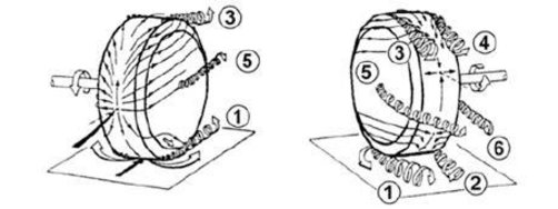
Fig. 3 All voritcies that come off a moving wheel
The concept is good, however it would require additional work to prove which we hadn’t done yet. Individual simulations would have to be run with and without the front canard, while analyzing the turbulent kinetic energy coming off that top left corner of the wheel. If the turbulent kinetic energy goes down with the front canard in the model, then that might be a good starting point for justifying the canard. In general, he did like that we were placing an airfoil in an empty spot to get more downforce since FSAE cars are more sensitive to downforce than drag.
For the radiator duct, he told us to look into shape factors since we could get some free performance through that. Nothing would beat testing the radiator with a heat load, though. He also told us that we could use anamometers to check the IRL flow speed/pressure at the radiator inlet/outlet for validation, which is a really good idea since anamometers are cheap and easy to implement. This would allow us to understand where to place the radiator in relation to the rest of the car for the airflow we need to hit the powertrain subteam’s thermal targets. An alternate method is to simply place the radiator directly in the velocity pathlines from full car simulations.
Finally, regarding center of pressure, we shouldn’t use every element of the car when outputting our CoP from Ansys. Just use the downforce generating devices, which for us at the current point in time are the front and rear wings.
One final note on our CFD was to try to target 15 million cells for our full car mesh. This would give accurate solutions based on his experience.
Lessons learned:
- Brute force method is just as good as genetic algorithm for 2D optimization
- Bring tutorials/team resources to competition, could get us points
- Look into 3D plots for 2D optimization
- Do full car simulations for nose cone, don’t design it in isolation, understand design features of nose cones
- Dynamic states can be studied IRL and/or in Ansys, both would be ideal
- Larger endplates generate more side force to the benefit of faster cornering, this should be researched and understood
- Outwash and upwash are 2 different philosphies completely, have a reason for picking one and design around it
- Understand canard-tire vortex interactions for drag reduction
- Look into shape factor and anamometers for radiator duct design and validation, respectively
- Omit everything from CoP calculations except for major downforce and drag generating devices
- Target 15 million cells for full car mesh