Suspension Considerations for Aerodynamics
I’d like to preface this design update with a huge thank you to everyone who works on designjudges.com. This collection of articles has been invaluable to myself and everyone at MAC Formula Electric over the past year and a half. It has opened our eyes to more things we need to consider in our subsystem designs.
Also, special thank you to Noah Dropkin for writing Aero Placement and Mounting. The following design update owes its contents to this article.
To anyone on MAC Formula Electric who may be reading this, read a relevant article on design judges before starting a new design!
Pitch, Roll, and Heave
In my first year of university, I never thought more of the ride height a race car was set at. 1 inch off the ground? Go for it. 1mm off the ground? Looks cool!
What I failed to realize at the time was how important suspension behaviours are for aerodynamic device placement, especially for ground effect devices such as the front wing and undertray. This importance is amplified due to FSAE Rules 2024 V.1.4.1.

Fig. 1 V.1.4.1
We are not a Formula 1 team. We do not have a skid block, and we can’t make sparks every other corner out of fear of being disqualified.
Your ride height is never your ground clearance in a dynamic state. There will always be pitch, roll, and heave to bring the chassis and front wing ever so slightly closer to the ground. This is very well illustrated from Aero Placement and Mounting.
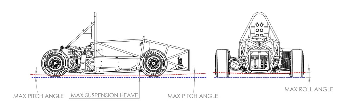
Fig. 2 Pitch, roll, and heave
From here I began finding the maximum pitch, roll, and heave values for EV5. After a discussion with the suspension subteam, we will not exceed 2deg of roll due to the addition of an anti-roll bar in both the front and rear. One value down.
Heave is another easy one. Worst case scenario we assume maximum heave allowable by the suspension, which for our springs is 57mm/2=28.5mm to allow at least 1 inch of wheel travel in rebound and compression to satisfy FSAE Rules 2024 V.3.1.1.

Fig. 3 V.3.1.1
Dive and squat angles took a little while to calculate, though. Firstly, we had to get a realistic value for our mu for our tires. The TTC had data for our slicks which is great, however under braking from 33.33mps we were pulling about 2.1G longitudinally (assuming no change in mu due to tire load sensitivity). Using intuition this was not correct.
After some digging through the TTC Round 9 documentation (as well as previous tire data analysis experiences) I realized this was due to a correction factor of 0.66 that had to be multiplied to the raw data to achieve realistic results for mu. After re-calculating we were acheiving 1.7G longitduinally with aero and 1.05G longitudinally without aero which seemed much more realistic. 1500N of downforce and 500N of drag were assumed at 33.33mps based on other teams claimed full car L/D ratios.
From here I was able to calculate the dive angle through basic kinematics.
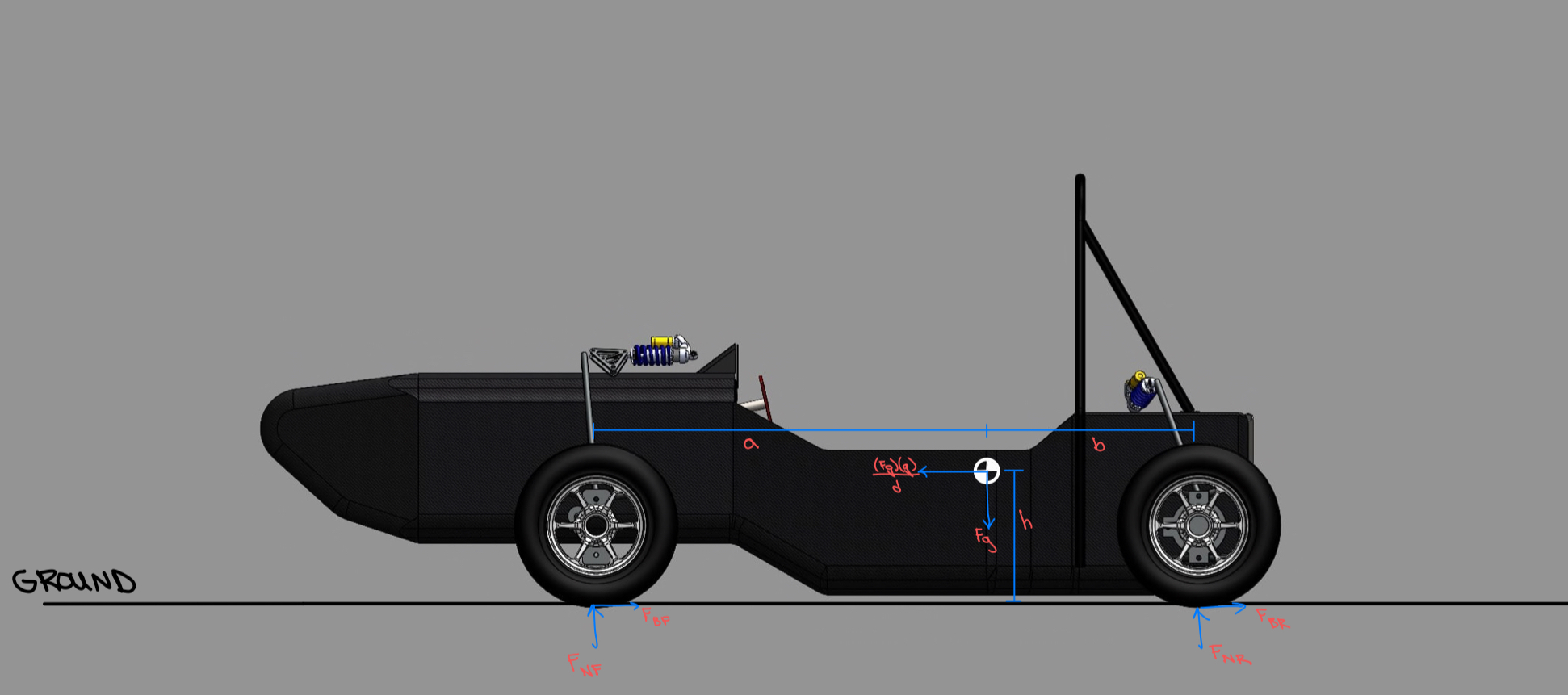
Fig. 4 FBD of EV5
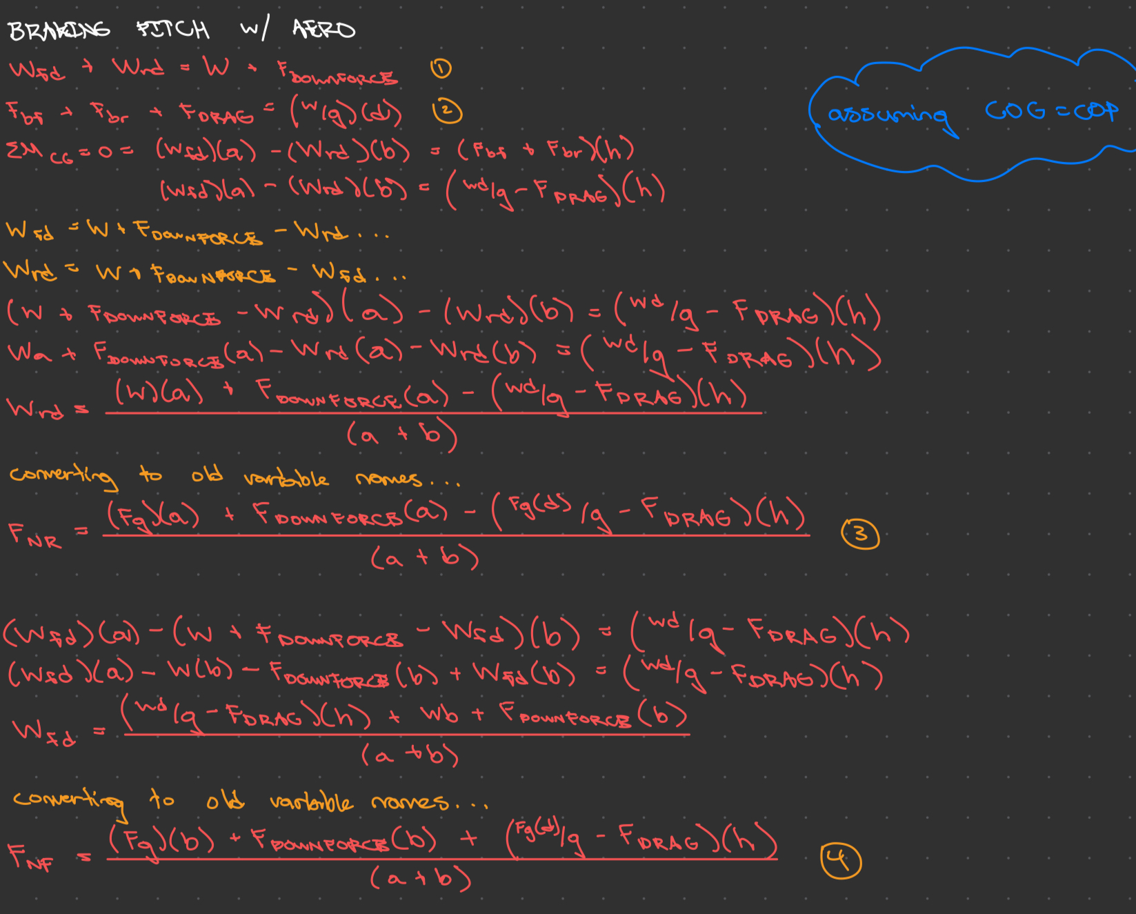
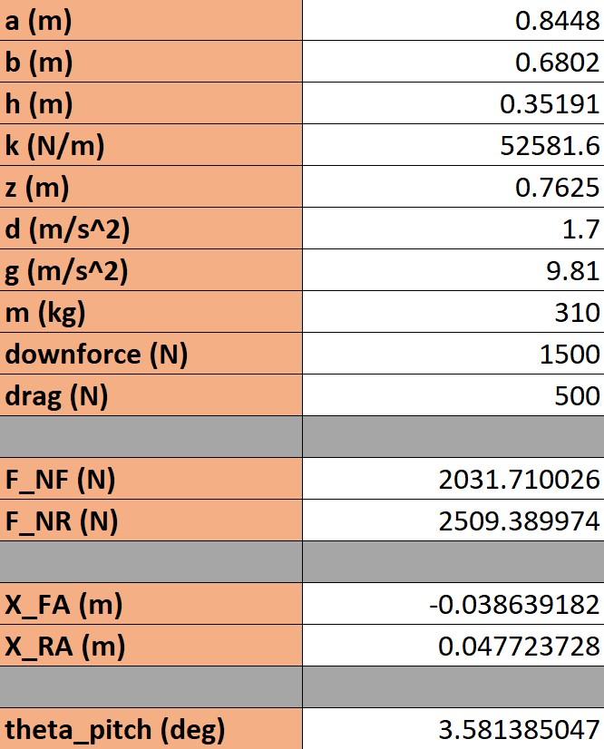
Figs. 5 and 6 Raw calculations (top) which I then transferred into an excel calculator (bottom)
For the time being we will assume squat angle of 3.5deg as well to save time. This should be calculated as well though.
Now that we have the pitch, roll, and heave values, we can create a representative ground clearance surface in Solidworks. After modelling a preliminary full car CAD with the front and rear wings placed in their bounding boxes from FSAE Rules 2024 V1 T.7.7.2, I immediately noticed a problem.
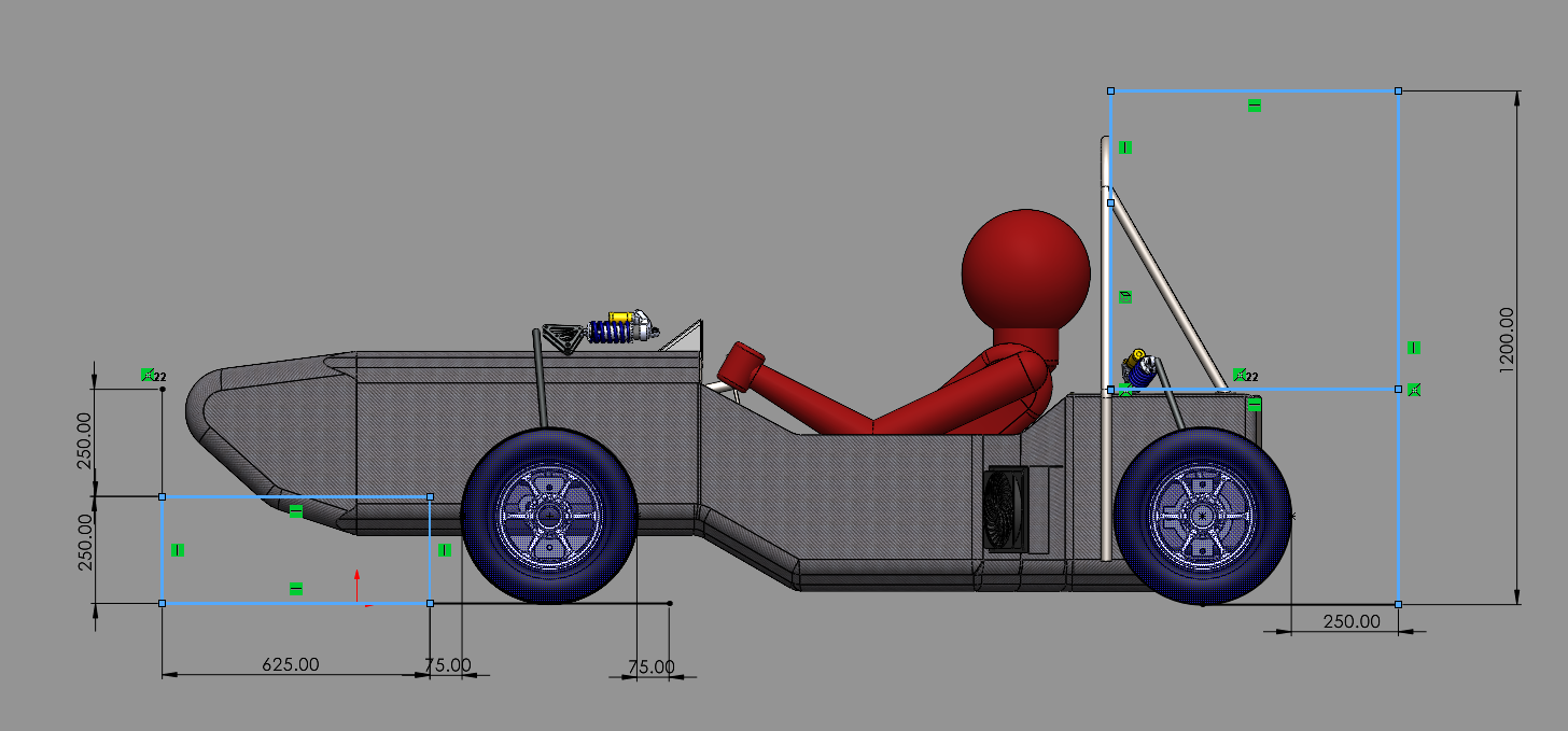
Fig. 7 Bounding boxes from T.7.7.2
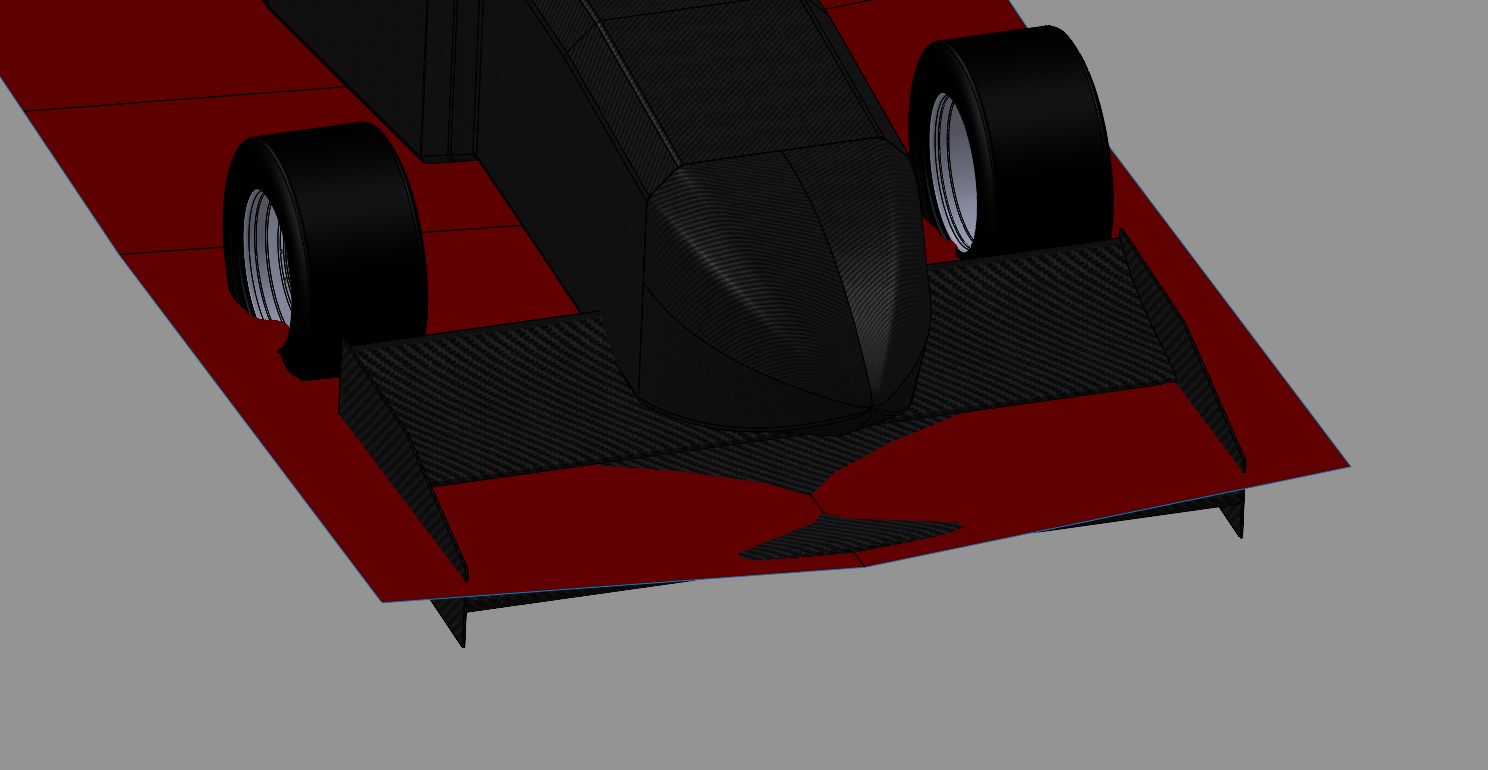
Fig. 8 The front wing fancies the ground
This prompted us to ask about the feasability of anti-dive geometry for EV5. After a brief discussion with the suspension subteam, 1.5deg of dive angle was achievable. Adjusting the effective ground clearance surface in the CAD to reflect this yielded encouraging results, along with reducing the chord and secondary element AoA of the front wing.
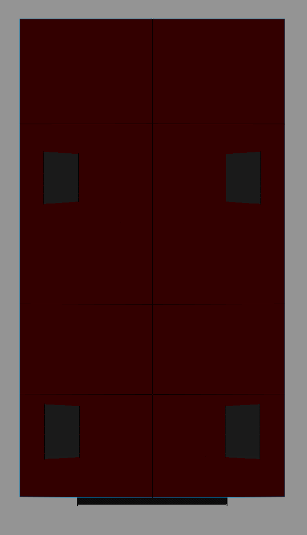
Fig. 9 No interference with the ground with 1.5deg of dive, 2deg of roll, and 28.5mm of heave
Full Car Model for Ansys
Once I was satisfied with the ground clearance I began making a simplified full car model for external analysis in Ansys. This was so that we could rule out any un-necessary geometry (e.g. small electrical switches, coolant tubing, etc.) that could be considered negligible for external airflow analysis. At the time of creating the CAD model there was no suspension CAD done, so we just modelled some simple arms in place of it.
At the time of making the model the suspension subteam was considering a double-wishbone pullrod system for the front, and double-wishbone pushrod system for the rear, so we modelled something to mimic that until they finalized their geometry and created a CAD model.
Some simple radiators were also modelled based on the motor drive subteam’s available design concept. Below are images of the final simplified model. Note that a driver has not yet been modelled, however it is in the works since it would definitely be a contributing factor to drag.
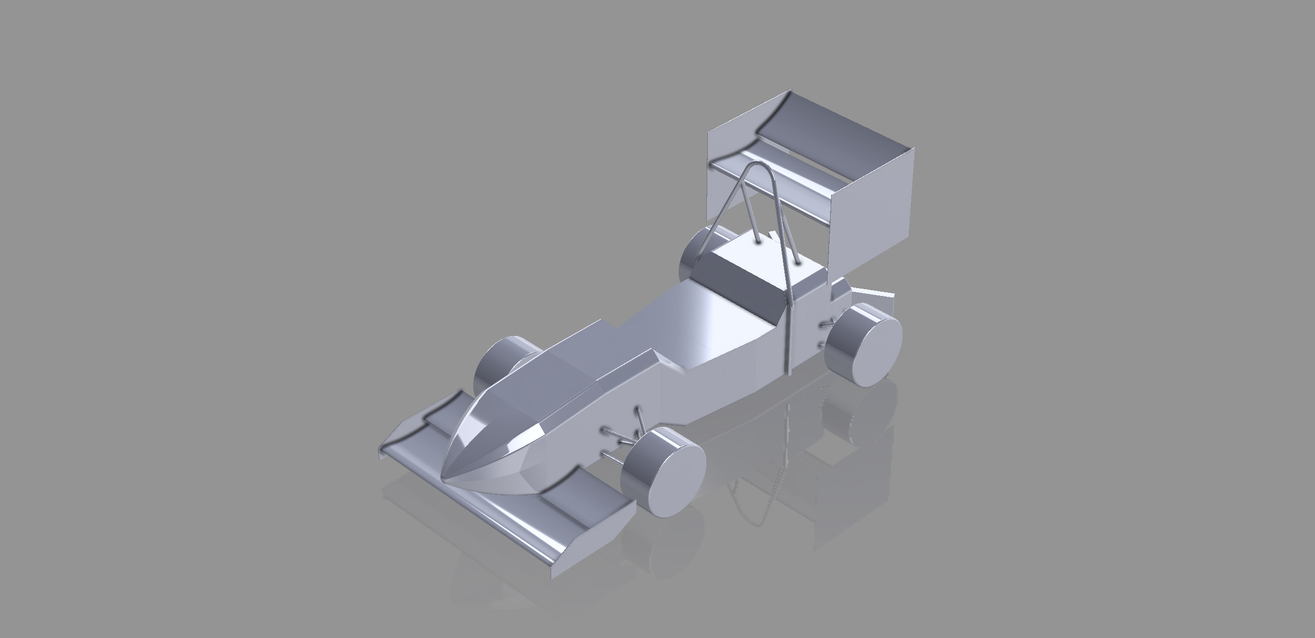
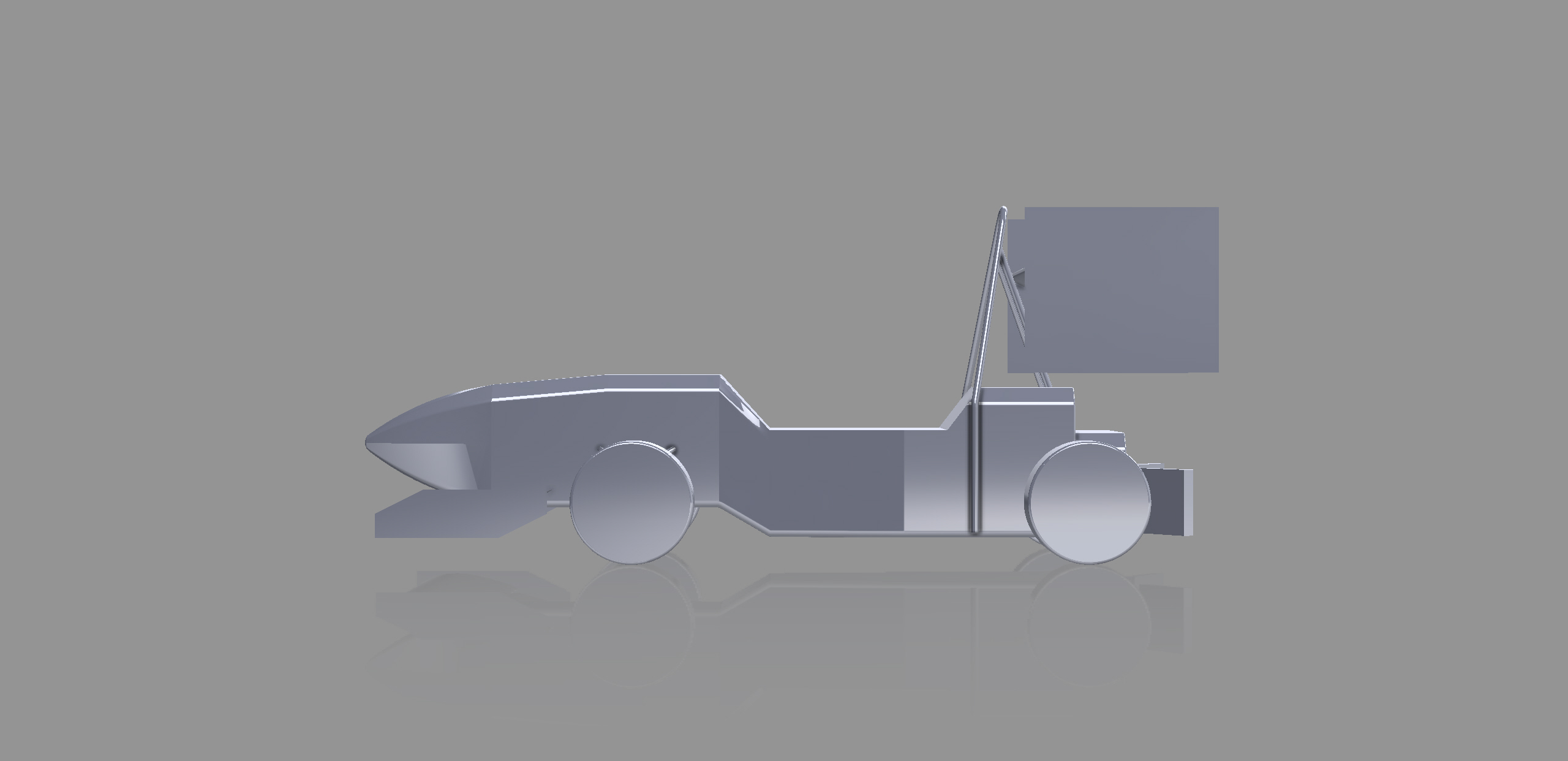
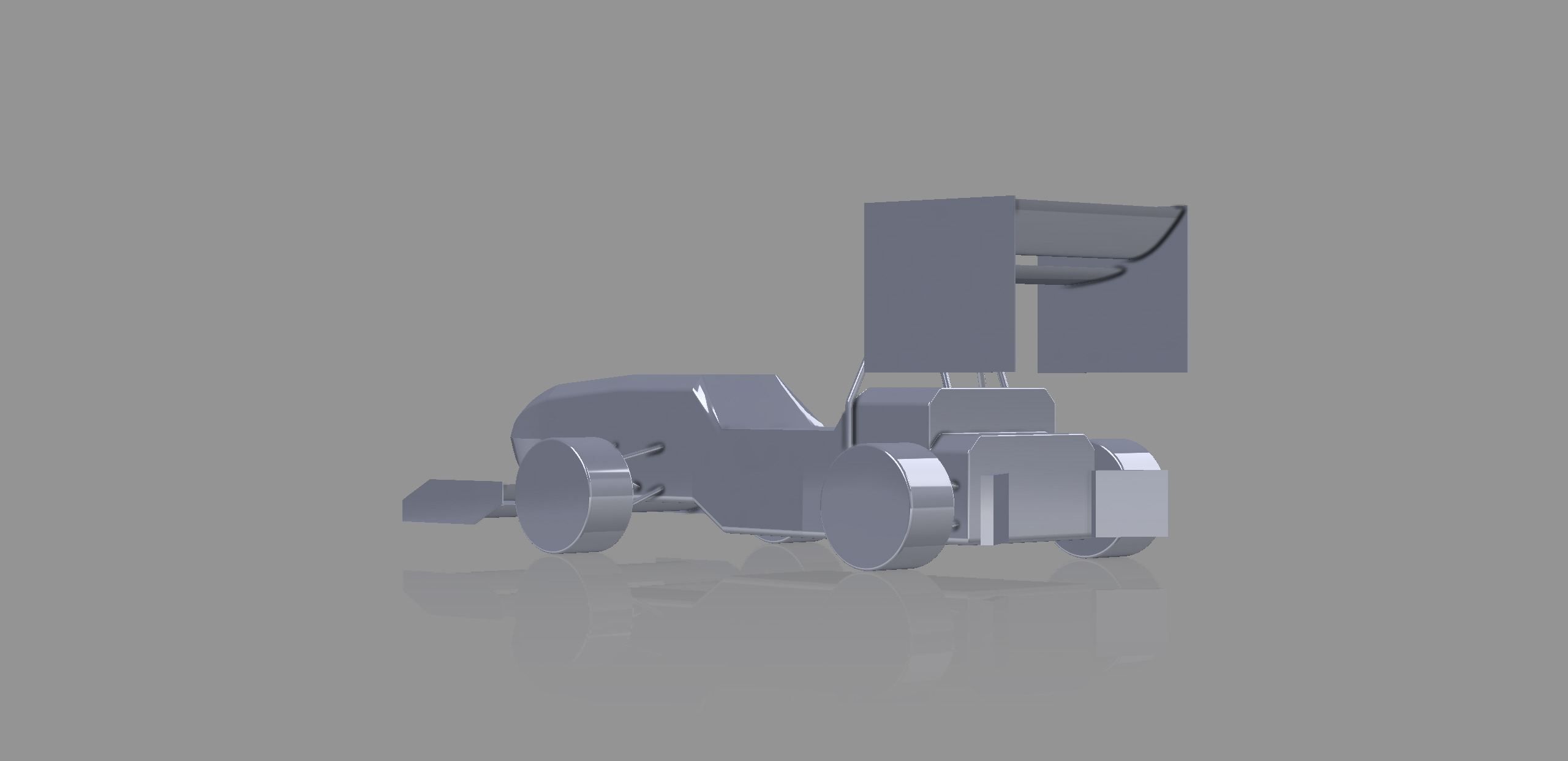
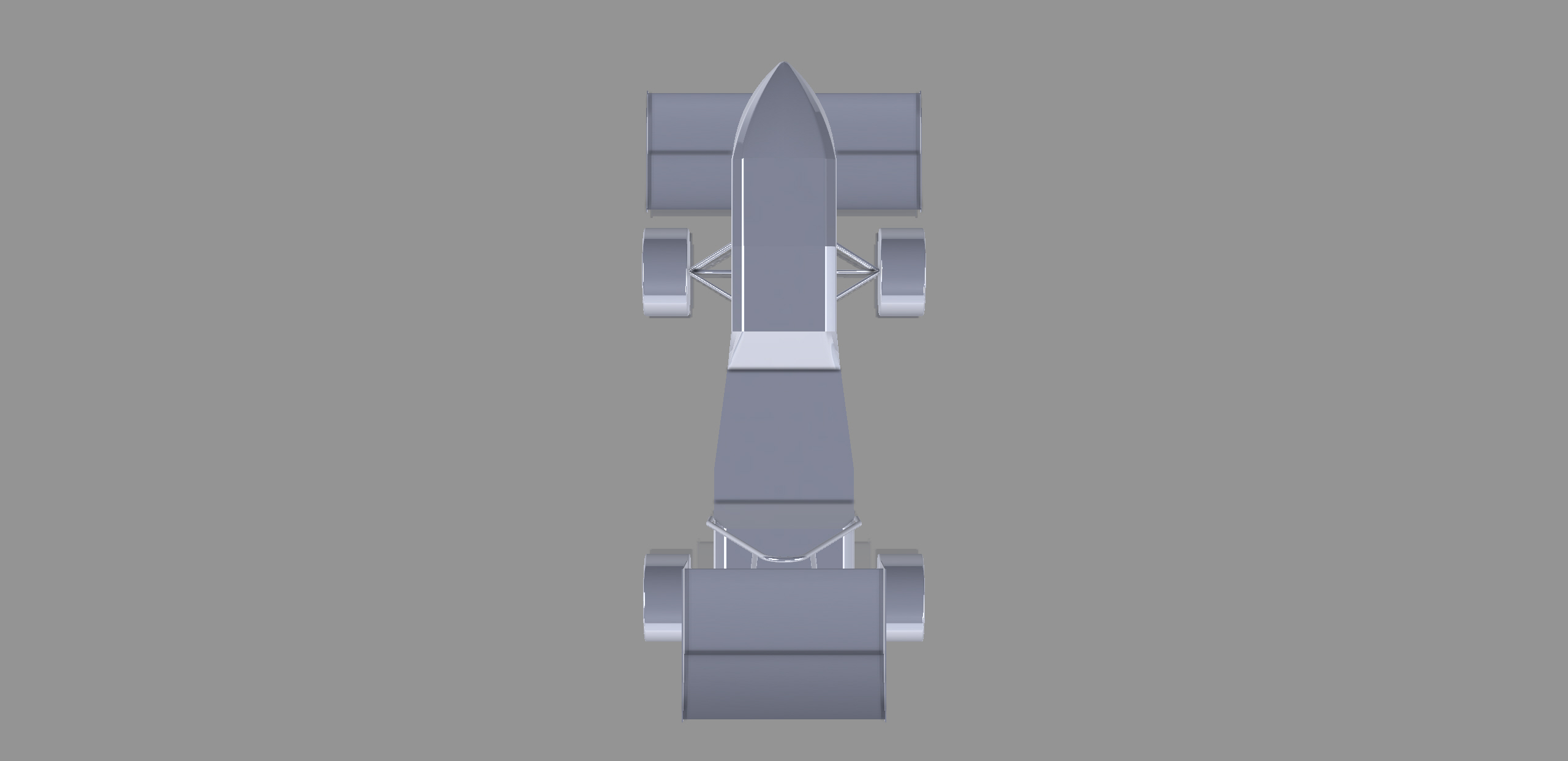
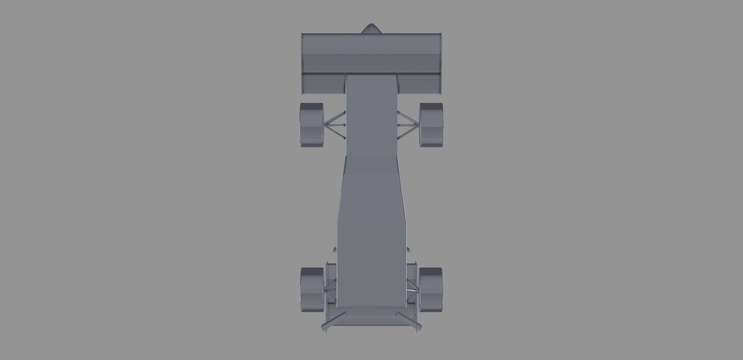
Figs. 10, 11, 12, 13, 14, and 15 Simplified full car model for Ansys meshing